Monday, 13 May 2013

2D Shadows Shader

This article is based on the following theories and samples. My implementation was merely ported across to C++/DirectX for learning purposes. All credit goes to the authors.

Recommended Reading:

Introduction


A couple of weeks ago, I published a post discussing dynamic 2D shadows, the theory regarding how one could create such an effect and provided a DirectX 9 sample for just that. This week I'll be discussing the same subject using a different method, this time based around graphics shaders.

I've already made a brief post dicussing how pixel shaders can be used to achieve some basic effects in XNA, but I'll recap the important bits for this entry. A shader is a small program that runs on the GPU (as opposed to the CPU like normal programs) and is typically used to perform shading and various other post-processing effects on a scene.

Vertex shaders are run once for each vertex in a primitive and usually deal with transforming 3D world coordinates into 2D screen coordinates, as well as processing any data needed for later stages of rendering. Pixel shaders, also known as fragment shaders, are run for each pixel in the rasterised output and deal with the actual shading of pixels as well as other post-processing effects.

The advantage of using shaders for this application is that shaders are much better at graphical operations, making them ideal for processing shadows in our scene. Additionally it frees up some CPU cycles, allowing us to use them for processing other aspects (such as game logic).

Shadow mapping
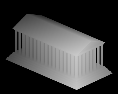
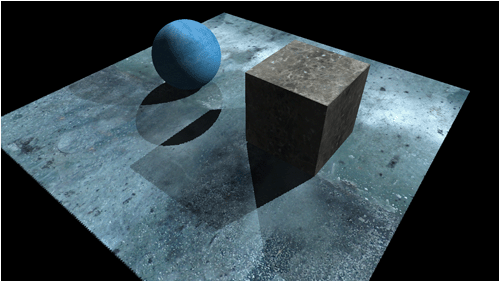
Scene from a light's view, Wikipedia

It's worth going over how shadows are typically processed in a regular 3D scene to give some insight into why certain steps are taken in this theory. The core idealogy for 3D shadow maps is to create a depth map from the light's perspective, which can then be used to determine whether pixels are in front of the nearest occluding object, or behind it.

One of the basic ways this could be done is to render the scene from the light's perspective, transforming points into the light's local space instead of the camera's. This way the Z value of each pixel can be used as a measure of depth and can be output using the colour (where pixels at one extreme are brighter than the other).

When rendering the final scene, pixels can then be transformed into the light's local space and compared against the value stored in the relevant position of the depth map. Closer pixels receive a colour value from the light and further ones simply receive an ambient value to simulate being in shadow.

Application in 2D


Unfortunately, rendering a scene in 2D from a light's perspective is not as straightforward as it is in 3D. You could probably find some way to convert X and Y coordinates into X and Z coordinates, but that's not the subject of this article. The theory outlined relies on three main steps:

First, the scene is rendered such that each pixel of an object which cast shadows (caster) is coloured based on its distance from the light source. Next, the scene is distorted such that all of the potential rays from the light source are aligned on the horizontal axis. Finally, this distorted image is compressed into a strip which stores the smallest (closest) values for each row, creating a depth map. This map can then be queried when rendering the scene to determine shading values, much like a traditional 3D shadow map.

Distance map

"Distance" map

The initial phase is relatively simple. Each object in your scene just needs to be transformed into the light's local space and then shaded based on its distance from the source. In my case I also scale the scene since my light radiuses may not always be the same size as the shadow map texture.

Here I utilise the fact that the position output from the vertex shader is in the [-1, 1] range, where (0, 0) is the centre of the render target and also where the light is. I simply pass a copy of this calculated position out as a texture coordinate (since Pixel Shader Model 2.0 doesn't support a position input semantic) and then use the length of that to determine the distance of the pixel.

Shader Code:
VS_OUTPUT DefaultVS(float4 position : POSITION, float2 tex : TEXCOORD0)
{
 VS_OUTPUT output;

 output.position = mul(position, g_worldViewProjMatrix);
 output.worldPos = output.position;
 output.tex = tex;

 return output;
}

float4 DistancePS(float2 worldPos : TEXCOORD1) : COLOR0
{
 float depth = length(worldPos);
 return float4(depth, depth, depth, 1);
}

Distorted map


Distorted map
The next phase is an intermediate step where we distort the distance map such that the rays from the light source are aligned along one axis instead of emitting radially. The vertical axes are also rotated 90 degrees and stored in a separate RGB channel such that all rays are horizontal.

The way this works is that coordinates are transformed into the [-1, 1] range (where 0, 0 is the centre of the texture) and the scene is divided into four quadrants (up, down, left and right). One coordinate is then scaled based on the absolute value of the other depending on which quadrant the point is in, causing points to tend towards the origin. These coordinates are then transformed back into the [0, 1] range and used as texture sampling coordinates for our scene.

Distortion plot in horizontal axis
This is difficult to explain in words, so I've provided a simple graph showing some example horizontal distortion coordinates. The brighter, dashed lines are the input coordinates after being transformed into the [-1, 1] range and the darker, solid lines are the output coordinates.

As we can see, when the x value is 1, the y value remains the same. However as x tends towards 0, so too does y. This means that even though we're drawing pixels along a horizontal row, we're actually sampling the texture along a diagonal emitting from the centre (the position of the light). A similar process happens in the vertical quadrants, except that the other coordinate (x) is scaled instead.


Shader Code:
float4 DistortPS(float2 texCoord : TEXCOORD0) : COLOR0
{
 // Transform coordinates into (-1, 1) domain.
 float u0 = (texCoord.x * 2) - 1;
 float v0 = (texCoord.y * 2) - 1;

 // As U approaches 0, V also tends towards 0.
 v0 *= abs(u0);

 // Convert back to (0, 1) domain.
 v0 = (v0 + 1) / 2;

 float2 coords = float2(texCoord.x, v0);

 // Store values in horizontal and vertical axes in separate channels.
 float h = tex2D(inputSampler, coords).r;
 float v = tex2D(inputSampler, coords.yx).r;

 return float4(h, v, 0, 1);
}

Depth map


Depth map, stretched for clarity
The next phase is to compress the distortion map into a 2-pixel wide strip, such that only the closest values in each quadrant remain. If you compare the stretched image to the right to the previous step, you'll see how the closest coordinates (green, red, black) are preserved in each half.

In Catalin's implementation, he goes about this by repeatedly downsampling his texture by half, taking the lowest values from pairs of pixels. One of the problems I see with this approach is that you need to have a different render target for each pass, all the way down to the final 2-pixel wide depth map. Another problem is that you end up sampling the same values multiple times. Not only do you have to sample and compare the entire texture once for the first downsample, but then you have to continually sample the remaining values until you get down to 2. This means that you almost end up sampling each pixel twice for the entire texture.

My implementation differs in that it has more passes, but each pixel is only sampled and compared once for the most part. It also only uses the input and output render targets, without any intermediate ones in between. The way it works is that we repeatedly sample a chunk of 8 pixels from the texture and output the lowest value from that batch of 8. We then then use a minimum blending operation to choose the smallest value between the destination and source pixels and write that to the render target. Finally, we offset the sampling position and repeat this for every chunk in the current section until we've sampled all the pixels and obtained the minimum value.

C++ Code:
// Convert distorted scene into a depth map.
device->SetRenderTarget(0, m_depthMapSurface);
device->SetRenderState(D3DRS_BLENDOP, D3DBLENDOP_MIN);

float largeStep = 1.0f / m_shadowResolution;
float smallStep = 1.0f / 2.0f;

effect->SetTechnique(handles[HANDLE_HREDUCTION]);
effect->SetTexture(handles[HANDLE_INPUTTEXTURE], m_tempMap);
effect->SetFloat(handles[HANDLE_HREDUCTIONSTEP], largeStep);

int chunks = (int)(m_shadowResolution / 2) / maxReductionSamples;

device->Clear(0, NULL, D3DCLEAR_TARGET | D3DCLEAR_ZBUFFER,
 D3DCOLOR_RGBA(255, 255, 255, 255), 1.0f, 0);

effect->Begin(&passes, NULL);

for (int c = 0; c < chunks; c++)
{
 // Calculate start point for this chunk set.
 float start = (largeStep / 2) + (c * (largeStep * 8));
 effect->SetFloat(handles[HANDLE_HREDUCTIONSTART], start);
 effect->CommitChanges();
   
 for (unsigned int i = 0; i < passes; i++)
 {
  effect->BeginPass(i);
  device->DrawPrimitive(D3DPT_TRIANGLESTRIP, 0, 2);
  effect->EndPass();
 }
}

effect->End();
device->SetRenderState(D3DRS_BLENDOP, D3DBLENDOP_ADD);
Shader Code:
VS_HREDUCT_OUTPUT HReductionVS(
 float4 position : POSITION, float2 tex : TEXCOORD0)
{
 VS_HREDUCT_OUTPUT output;

 output.position = mul(position, g_worldViewProjMatrix);

 for (int i = 0; i < HREDUCTION_MAX_STEPS; i++)
 {
  output.tex[i] = float2(tex.x + g_hReductionStart
   + (g_hReductionStep * i), tex.y);
 }

 return output;
}

float4 HReductionPS(VS_HREDUCT_OUTPUT input) : COLOR0
{
 float2 colour = (float2)tex2D(inputSampler, input.tex[0]);

 for (int i = 1; i < HREDUCTION_MAX_STEPS; i++)
  colour = min(colour, (float2)tex2D(inputSampler, input.tex[i]));

 return float4(colour, 0, 1);
}

Shadow map


Final shadow map for a light
The final phase is to draw our completed shadow map. This step is relatively straightforward, for each pixel we get the relevant value from our depth map and compare the distances from the centre. If the current pixel is closer then we shade it in brightness, if it's further then we shade it as black. We also simulate light attenuation by using the distance of the lit pixels to determine how bright they are.

The only not-so-straightforward bit is determining and getting the relevant depth map value. For this, we simply transform the x and y coordinates into the [-1, 1] range again and compare their absolute values. We then apply the inverse distortion operation to either x or y, depending on which was greater, and sample the relevant depth map channel at those coordinates. Another important thing to note is the inclusion of a 1-point bias to the pixel distance to prevent shadow acne.

Shader Code:
float4 ShadowMapPS(float2 texCoord : TEXCOORD0) : COLOR0
{
 float distance = length(texCoord - 0.5f) * 2;
 distance *= 512.0f;
 distance -= 1;

 // Transform coordinates into (-1, 1) domain.
 float u0 = (texCoord.x * 2) - 1;
 float v0 = (texCoord.y * 2) - 1;

 float shadowMapDistance = abs(u0) > abs(v0)
  ? GetShadowDistanceH(texCoord) : GetShadowDistanceV(texCoord);

 // Render as black or white depending on distance and depth value.
 float light = distance < shadowMapDistance * 512.0f
  ? 1 - (distance / 512.0f) : 0;

 float4 colour = light;
 colour.a = 1;

 return colour;
}

Final light map


Final scene light map
After we have each light's shadow map, we follow a similar process to the previous dynamic 2D shadows method. We draw each shadow map at its relevant position and colour on the light map texture and then we render the light map over the top of our scene using the Zero and Source Colour blending modes for the Source and Destination textures respectively. As before, this means that for each pixel in our scene, only the colours in the light map are rendered at that position.


Source code and comments


I greatly prefer this method over the previous one. Not only is the result of better quality and easier to adjust and add new features to, but the potential FPS gain is massive. The previous implemention of dynamic 2D lights had an FPS count of a little over 800 in release mode. This new approach has roughly 1400 FPS in release, almost double the previous amount. Granted, the GPU in my development computer is pretty decent, but it goes to show what sort of gains you can get by offloading some work from the CPU.

An optimisation that could be made is that currently each light owns its own shadow, distortion and depth map textures. At least for the distortion and depth maps, these textures could be shared among multiple lights with the same shadow resolution since the values are only needed during the rendering of a light's shadow map and can be discarded as soon as it is complete. Another optimisation is that static lights could skip redrawing their shadow map until they move. Only 2 of the 6 lights in the sample ever move, so it would be relatively simple to add a check to skip redrawing if the light hasn't moved since the last call.

In Catalin's sample, he also applies a distance-based gaussian blur to simulate the way that shadows tend to get sharper the closer they are to the light source (as well as smoothing out the rough edges on shadows). My implementation skips this step, as I was aiming for a result comparable to my previous sample. See his article for an implementation for this effect.

Credits:
George - Wizard Sprite
Studio Evil - Ground Texture

Source:
Sample Archive
DirectX 9 Redistributable

Friday, 26 April 2013

Dynamic 2D Shadows

This article is based on the following theories and samples. My implementation was merely ported across to C++/DirectX for learning purposes. All credit goes to the authors.

Recommended Reading:

What are dynamic 2D shadows

Monaco: What's Yours is Mine
They are an aspect of lighting for 2D games (sidescrolling, top-down, etc.) where as the light source moves through the environment, shadows are updated and cast in real-time. As such, you can get some quite impressive effects as you walk past a series of columns for example.

Of course, this aspect does not need to be used just for lighting specifically. Monaco is a game which uses this concept for the player's field of view, such that you can only see the parts of the level that your character actually has line of sight with.

How you could implement it

There are two main aspects to consider when using this approach. The first is the concept of Render to Texture, where instead of rendering to the usual backbuffer you render to a separate texture; and the second is Texture Blending, where you control how multiple textures are blended together for different visual effects. It's important that you have a basic grasp of these techniques, so I'd recommend reading up on them if you're not too sure what they mean.

Our game rendering code is broken up into three phases. First we render what's known as a lightmap to a separate render texture, then we render our level geometry to the backbuffer and finally we then blend the backbuffer with the lightmap to create our final scene. Since creating the lightmap requires the most work, it will be the focus for this article.

Creating a lightmap

A lightmap is simply a map of the light (and consequently dark) areas in a scene. In our case, it's simply a coloured texture which we combine with our scene, where the dark areas of the lightmap are rendered in ambient lighting and the bright areas are rendered according to their colour.

Creating shadow primitives
In order to create a light map, we need to create geometry for our shadows. For each light and object pair, we loop through each of the object's faces and compare whether it is facing the light source. This is done by taking each face's normal and using the dot product to compare it to the direction of the light (greater than 0 means it's facing the light and less than 0 means it's facing away).We then take the points which make up these faces and project them away from the light source to create a shadow primitive.

If we were to simply loop through each light, render a simple feathered circle texture for each and then render a black primitive behind each of our objects for shadows, we wouldn't be able to blend multiple light sources together (as the black would override any other colour already there). As such, in order to create our lightmap, we're going to use a little trick to control what parts of the light texture are rendered.

First, we render the shadow primitives to the texture's alpha channel as 0. The alpha channel controls how transparent a texture is, and since the lightmap will always be completely opaque we can use it as a form of temporary storage instead. To do this in DirectX 9, we set the following render state parameter before drawing our primitives.

device->SetRenderState(D3DRS_COLORWRITEENABLE, D3DCOLORWRITEENABLE_ALPHA);

Then we render our light texture using a blending operation where the amount of light texture added depends on the target's alpha. For DirectX 9, the way we achieve this is by setting the device's render state blending parameters before drawing our light texture. We also reset the ColorWriteEnable parameter so we can render the light texture's RGB values.

device->SetRenderState(D3DRS_COLORWRITEENABLE, 0x0000000F);
device->SetRenderState(D3DRS_SRCBLEND, D3DBLEND_DESTALPHA);
device->SetRenderState(D3DRS_DESTBLEND, D3DBLEND_ONE);

A lightmap created from 6 lights
Source Blend is the factor for the texture we're rendering (light texture), where as Destination Blend is the factor for the rendering target (lightmap). Setting the Source Blend Factor as Destination Alpha means that the amount of the source texture used is dependant on the render target's alpha. Setting the Destination Blend as ONE means that 100% of the render target is always used. By default, the Blending Operation is set to ADD, which means that the source factor is added to the desination. As such, this means that our new light value is added to any existing value at that position, rather than overwriting it.

If we repeat this process for each light we can create a lightmap containing all of our lights, correctly shadowed and blended where two lights meet. Don't forget to clear the alpha channel between drawing each light so that our shadow data doesn't carry across into the following lights. Unfortunately both the Clear() and ColorFill() methods in DirectX ignore the ColorWriteEnable parameter, so you have to manually render a full-screen quad if you want to clear the lightmap's alpha channel.

Combining the lightmap with the scene

After rendering your scene geometry, we can then combine it with the lightmap to form the final lit scene. To do this, we use another blending operation to control how much of the scene colour we render. Specifically, we render our target texture where the amount of target texture used depends on the lightmap's colour or RGB values. To this in DirectX 9, we set the device's render state blending parameters to the following values.

device->SetRenderState(D3DRS_SRCBLEND, D3DBLEND_ZERO);
device->SetRenderState(D3DRS_DESTBLEND, D3DBLEND_SRCCOLOR);

Scene combined with lightmap
In this case the Source Blend Factor is ZERO, meaning that none of the source texture is used. The Destination Blend Factor is set as SRCCOLOR though, which means that the RGB components used for the destination are the same as those in the source texture. This means that any areas in a scene where the lightmap is red for example will only render their red components.

An interesting thing to note is the effects of multiple light sources. In the picture shown, you can see how some of the shadows from the blue light are rendered as more pink since they're still receiving light from the pink source. Light is also correctly blended where the two lights meet, forming a purple area.

Source code and comments

While this method does produce very impressive visual results, it can also be quite taxing for the framerate. Every frame we have to compare every light to every object in the scene and calculate shadows for each of them. In my sample, adding just one extra hull caused the FPS to drop by 60 frames. If you consider how sparse the scene is, you can already begin to imagine the problems you'd have with using this solution in a complex game.

I've attempted to optimise the code by batching all of the shadows into one draw call for each light, but even then the performance save was only some tens of frames per second. There may be other ways to increase performance though, so if you have any ideas then do feel free to share them. You should find an executable in the Release folder, which will need the latest DirectX 9 redistributable or SDK to run.

Credits:
George - Wizard Sprite
Studio Evil - Ground Texture

Source:
Sample Archive
DirectX 9 Redistributable

Tuesday, 9 April 2013

Updates and Getting Started with DirectX

What I've been up to since my last update:

During late January and mid February, I'd organised a short internship at a local company to get some practical, hands-on experience with working in a professional environment making games. It was a great experience, the people I was working with were really friendly and it was nice to get an idea of how social a work environment can be.

I had a few tasks during my weeks there, but the area I spent the most time working on was a Pool game they had for Samsung mobiles. It was interesting learning a new development environment and spending time on a slightly different project than I was used to. Among some fixes for newer versions of Bada and some work on making a menu for achievements, I spent a lot of time creating an AI player so the game could be played by yourself. (You can see a video of the AI in action on the Portfolio page.)

Coming away from internship:

Microsoft XNA Logo
Around the time I was doing my internship, I became aware that Microsoft is effectively dropping XNA. Now while XNA isn't "dead" so to speak (you can still make games using it and there is an open source implementation called MonoGame) it prompted me to start considering how I want to proceed as a game developer.

Typically speaking, most console developers work in C++ for their game code and look for experience with APIs like DirectX or OpenGL, while mobile developers are more frequently using tools like Unity3D (a tool I also had some time with during my internship). Looking through job postings, it was very rare to see anyone specifically mention XNA experience as a desired quality.

As such, I made the decision that once I'd gotten my current project to a reasonable release state, I'd shift focus to either DirectX or Unity3D in order to continue my path as a game developer. Considering how much I'd been focusing on C# since leaving university, I was leaning towards DirectX so I could brush up on my C++.

Getting started with DirectX:

I found that getting started with DirectX was less straightforward than with XNA. XNA has an official portal with several tutorials and samples for beginners to look through, as well as hundreds of other tutorials available on the web. DirectX's main source of documentation is the SDK itself and its sample browser. That's not to say there aren't tutorials available for DirectX online, there are several, but don't expect it to be as straightforward as XNA.

The reason for that is simple. Where as XNA is a tool kit, which gives you a lot of boilerplate code to get started with, DirectX is a collection of APIs and expects developers to code for themselves. What does this mean in practical terms? Take this example. In XNA, when you create a new project you're given a game window with frame methods for Updating and Drawing your elements. In DirectX, you have to create that window yourself and specify all the functionality you want.

It's been quite the learning experience, though I feel like I've gotten a lot of helpful experience from it. Getting reaquainted with memory management is probably one of the more common areas I've spent time with. It's certainly useful to be able to delete a block of memory and know that it's gone the second the line executes. Another area I've had some time with is vertex management and shaders. I'd only recently dabbled with it in XNA, so it was interesting to see how similar it was in DirectX.

Some useful tutorials:

RasterTek "Multiple Light Shadow Mapping" Tutorial
I don't think I could have gotten as familiar as I am with DirectX currently if it weren't for these tutorials. These really helped break it down to simple, easy to comprehend chunks that allowed me to focus on what I was coding and fundamentally understand how it impacted the overall program.


What's happening next?

Once I've finished my current set of tutorials, I plan to make something very basic in DirectX which I'd always wanted to get around to with XNA. It will probably be more of a tech demo than an actual game, but it's something I originally wanted to include in Project Lead before I decided to move on.

Tuesday, 22 January 2013

Project "Lead" Update #5

Update #4: http://ahamnett.blogspot.co.uk/2012/11/project-lead-update-4.html

What features have you added since the last blogpost?

Generally the focus has been on polishing the mechanics and systems already in place, as well as continuing to introduce and update assets for existing content. In particular, I've been working on implementing some more environmental entities like props and decals to further improve the level.


The time I've spent refining the weapon mechanics, AI and gameplay has really benefitted the overall experience. In addition, it's always impressive to see how much simple content additions can improve the overall effect. In particular was the addition of the ambient music and the road crossings, both of which really helped in making the level feel like less of a box and more of an actual location.

What technical aspects have you explored for these features?

One aspect that came up a lot during these past few weeks was the idea of resolution independancy, i.e. making the game work on multiple resolutions and still look roughly the same (HUD not taking up more/less room, view distance not being larger/smaller depending on resolution).

I had to spend a lot of time working with the rendering code to ensure that both sprites and primitives could scale to fit the resolution. I ended up rewriting most of the SpriteBatch rendering to use the same projection matrix as the primitives, ensuring that they were scaled the same way.

Lead v0.072 - 1080p
Lead v0.072 - 720p
Further, it's also helped me brush up on more fundamental programming concepts such as interfaces. I restructured the drawing code into two lists, one for primitives and another for sprites. As such, I redesigned entities to inherit either an IDrawableSprite or IDrawablePrimitive interface to help easily determine which of the lists any entity would need to be in.

What features are you planning on working on next?

One of the last things I worked on recently was a very basic particle emitter system. Currently it's an extremely rough implementation that's only used to create simple blood splatter effects when characters are hit. I plan to continue working on this system, refining the implementation and adding more types of effects. In particular, I want to create hit effects for props and other static objects by using a part of the texture as the particle sprite, similar to Minecraft.

As always, I also want to continue adding assets to the game. I want to finally implement some proper player and enemy sprites, as well as continuing to populate the level with props and decals. I'm also considering adding some more weapons as currently there are only 3, including the starting pistol. I may investigate projectile weapons such as grenade and rocket launchers to create a more varied arsenal.

Thursday, 3 January 2013

Pixel Shaders for Dummies

The goal of this post will be to give an extremely quick introduction to pixel shaders in XNA, what sort of basic things you can do with them and some other information.

What is a Pixel Shader?

A shader is a program or function that runs on the GPU instead of the CPU. The name comes from its primary use, which is to shade textures on a pixel-by-pixel basis. Typically, they're used for rendering lighting and shadows in a scene, however in recent years they've also been used for producing special effects and other forms of post processing.

The main advantage of pixel shaders is that most of the work is done on the GPU instead of the CPU, and that the GPU is very fast at performing these sorts of operations. In addition, their versatility allows all sorts of effects to be created with the right knowledge.

What sort of effects can you create?

Almost any effect you can think of in a graphics application, such as Photoshop, can be created using shaders. For the subject of this post though, we'll be focusing on alpha blending or "masking".

Image courtesy of Survarium.

Alpha blending is a texture editting technique where certain areas of a texture are made transparent or "masked" using another texture. In the example above, the image on the left had the mask in the middle applied which resulted in the image on the right. The black areas on the mask made the picture transparent, while the white areas did not affect it. The grey areas in between produced a gradual fade from opaque to transparent.

Writing the Shader

Before we can start writing our game code, we need to create our shader. This shader's going to be relatively simple, it will have two external variables (the screen's texture and the mask) and will multiply each pixel in the screen by the equivalent pixel's brightness in the mask.

First, we need to create an effect file. Right-click on your solution's Content project and click "Add", followed by "New Item...". Select "Effect File", call it what you want (alpha_map.fx, for example) and click "Add". XNA automatically generates some boiler plate code, but not much of it is directly relevant to this example so delete it.

Now that we have a clean slate, we're going to create our two external variables.
// The texture we are trying to render.
uniform extern texture ScreenTexture;  
sampler screen = sampler_state 
{
    Texture = <ScreenTexture>;
};

// The texture we are using to mask.
uniform extern texture MaskTexture;  
sampler mask = sampler_state
{
    Texture = <MaskTexture>;
};
This creates two paramaters for our shader, ScreenTexture and MaskTexture. The former is used to reference the current, unshaded texture and the latter will allow us to initialise and even change the mask during runtime.

Next, we need a quick function to determine the brightness of a pixel in our mask texture.
float MaskPixelBrightness(float4 inMaskColour)
{
    // Get the min and max values from the pixel's RGB components.
    float maxValue = max(inMaskColour.r, max(inMaskColour.g, inMaskColour.b));
    float minValue = min(inMaskColour.r, min(inMaskColour.g, inMaskColour.b));

    // Return the average of the two.
    return (maxValue + minValue) / 2;
}
Because shader pixel data is typically stored as a float4 RGBA value, there's no way to directly determine how "bright" the pixel is. This implementation uses the HSL "bi-hexcone" model as described on Wikipedia, which is simply the average of the largest and smallest values from the RGB components.

Now we move onto our main shader function, the part which will actually do the per-pixel shading.
float4 PixelShaderFunction(float2 inCoord: TEXCOORD0,
    float4 inColour : COLOR0) : COLOR
{
    // Get the colour value at the current pixel.
    float4 colour = tex2D(screen, inCoord);

    // Get the brightness value at the current mask pixel.
    float maskBrightness = MaskPixelBrightness(tex2D(mask, inCoord));

    // If a Color argument has been passed into SpriteBatch.Draw(), we
    // multiply the value by it to hue. Then we multiply by the brightness
    // value of the mask to hide the appropriate pixels.
    colour.rgba = colour.rgba * inColour.rgba * maskBrightness;

    // Return the updated pixel.
    return colour;
}
The first couple of lines get the RGBA value of the texture and the brightness value of the mask respectively. The next line multiplies the pixel value by the Color argument (if one has been passed in SpriteBatch.Draw()) and the brightness value. This has the effect of allowing textures to be hued as normal, as well as masking the texture.

Finally, we write the technique for the shader to use when rendering.
technique
{
    pass P0
    {
        // Compile as version 2.0 for compatability with Xbox.
        PixelShader = compile ps_2_0 PixelShaderFunction();
    }
}
A shader can have multiple techniques and each technique can have multiple passes. For our simple shader though, only one technique and pass are needed. We compile as Pixel Shader 2.0 so that the shader is compatible with Xbox as well as PC.

Creating a passive mask

Now that we have our shader, we can start writing some game code. First we'll add the appropriate content variables and load them in LoadContent().
        GraphicsDeviceManager graphics;
        SpriteBatch spriteBatch;

        Effect alphaShader;
        RenderTarget2D wipeRender;
        Texture2D planetTexture;
        Texture2D wipeTexture;

        public Game1()
        {
            graphics = new GraphicsDeviceManager(this);
            Content.RootDirectory = "Content";
        }

        /// 
        /// LoadContent will be called once per game and is the place to load
        /// all of your content.
        /// 
        protected override void LoadContent()
        {
            // Create a new SpriteBatch, which can be used to draw textures.
            spriteBatch = new SpriteBatch(GraphicsDevice);

            // Load our various content.
            alphaShader = Content.Load<Effect>("alpha_map");
            planetTexture = Content.Load<Texture2D>("planet");
            wipeTexture = Content.Load<Texture2D>("wipe");

            // Initialise the render target to be the same size as the planet.
            wipeRender = new RenderTarget2D(graphics.GraphicsDevice,
                planetTexture.Width, planetTexture.Height);

            // Set the render target to be blank initially.
            graphics.GraphicsDevice.SetRenderTarget(wipeRender);
            graphics.GraphicsDevice.Clear(Color.White);

            // Go back to drawing to the screen again.
            graphics.GraphicsDevice.SetRenderTarget(null);
        }
Most of this should be pretty explanatory except for the RenderTarget2D variable. This is going to be our "canvas" when we're creating our mask and will then get passed in as the MaskTexture paramater for our shader. As such we want the render target to be the same size as our planet and we initially want it to be completely white, so that the texture is drawn in full by default.

Next, we're going to write a method to draw our render target. Add this to the bottom of your Game1 class.
        /// 
        /// Update the wipe texture position.
        /// 
        private void UpdateWipeMask()
        {
            // Tell the graphics device we want to draw to our seperate render target,
            // instead of the screen, until we tell it otherwise.
            graphics.GraphicsDevice.SetRenderTarget(wipeRender);

            // Clear the render for the update.
            graphics.GraphicsDevice.Clear(Color.Transparent);

            spriteBatch.Begin();

            // Draw the mask in its current position.
            spriteBatch.Draw(wipeTexture, new Rectangle(-planetTexture.Width,
                    0, planetTexture.Height * 5, planetTexture.Height),
                Color.White);

            spriteBatch.End();

            // Go back to drawing to the screen again.
            graphics.GraphicsDevice.SetRenderTarget(null);
        }
This method simply sets the graphics device to draw to the render target we set up earlier, then draws our mask texture onto it. The X offset is because my mask texture has a white square at the start, so I offset slightly so that the gradient part of the mask is shown instead. My mask is also smaller than my planet texture, so I scale the rectangle to fit it.

Now we call the method in Update() and add the code to Draw() which will allow us to render our masked texture.
        /// 
        /// Allows the game to run logic such as updating the world,
        /// checking for collisions, gathering input, and playing audio.
        /// 
        /// Provides a snapshot of timing values.
        protected override void Update(GameTime gameTime)
        {
            // Allows the game to exit
            if (GamePad.GetState(PlayerIndex.One).Buttons.Back == ButtonState.Pressed)
                this.Exit();

            UpdateWipeMask();

            base.Update(gameTime);
        }

        /// 
        /// This is called when the game should draw itself.
        /// 
        /// Provides a snapshot of timing values.
        protected override void Draw(GameTime gameTime)
        {
            GraphicsDevice.Clear(Color.Black);

            // Set the value of the alpha mask.
            alphaShader.Parameters["MaskTexture"].SetValue(wipeRender);

            // Start SpriteBatch using our custom effect.
            spriteBatch.Begin(SpriteSortMode.Immediate,
                BlendState.AlphaBlend, null, null, null, alphaShader);

            // Draw the planet texture, including any mask in alphaShader.
            spriteBatch.Draw(planetTexture, new Vector2(208, 24), Color.White);

            spriteBatch.End();

            base.Draw(gameTime);
        }
As you can see, this step is relatively straight forward once we've done all the preliminary coding. Each frame the draw method is called to set our mask texture and then this texture is passed during drawing.


This type of mask isn't really that useful though, as you can just bake the mask into the texture you're using rather than having to use pixel shaders. Additionally, some people will notice that having the render target update every frame isn't very optimal for our uses. This leads us onto our next topic.

Creating an active mask

Having a mask that moves is much more practical and will allow us to achieve effects which are not so simple otherwise. This time we'll create a wipe effect, where the texture gradually fades off from left to right and back on again. Thankfully, making the mask move is not so difficult given what we already have.

First, we need to add a variable to our game which will store the position of the mask.
        GraphicsDeviceManager graphics;
        SpriteBatch spriteBatch;

        Effect alphaShader;
        RenderTarget2D wipeRender;
        Texture2D planetTexture;
        Texture2D wipeTexture;

        int wipeX = 0;
Now we need to modify our mask drawing method to update the position each time it draws.
        /// 
        /// Update the wipe texture position.
        /// 
        private void UpdateWipeMask()
        {
            // Wipe from left to right.
            wipeX += 6;

            // Each time we reach the end of the texture, reset to loop the effect.
            if (wipeX >= 0) wipeX = -planetTexture.Width * 4;

            // Tell the graphics device we want to draw to our seperate render target,
            // instead of the screen, until we tell it otherwise.
            graphics.GraphicsDevice.SetRenderTarget(wipeRender);

            // Clear the render for the update.
            graphics.GraphicsDevice.Clear(Color.Transparent);

            spriteBatch.Begin();

            // Draw the mask in its current position.
            spriteBatch.Draw(wipeTexture,
                new Rectangle(wipeX, 0, planetTexture.Width * 5, planetTexture.Height),
                Color.White);

            spriteBatch.End();

            // Go back to drawing to the screen again.
            graphics.GraphicsDevice.SetRenderTarget(null);
        }
You'll notice the only real difference to the method is that the wipeX variable we declared is increased and that value is used as the X position when drawing. I also clamp the variable so that when it reaches 0 (where the left side of the mask is parallel with the left side of the texture) it resets back to the end.


That's all there really is to it. You can improve the performance by moving the call to UpdateWipeMask() to Draw() instead, that way you only update the mask every time it's drawn. The only problem is that this then means that the speed of the wipe is dependant on the framerate (slower machines won't draw as quickly and therefore won't update the mask as fast). This would be suitable for background effects where the speed isn't so important though (like a glowing effect on a powerup).

Creating a dynamic mask

The final piece of the puzzle is to have the mask react to player input. For this part we will make it so that a crater is added to the mask when the player clicks on the planet, hiding that area of it. Since this is slightly different than the last two approaches, it will take a bit more work to implement.

First, we need to add some additional variables and initialise them.
        GraphicsDeviceManager graphics;
        SpriteBatch spriteBatch;

        Effect alphaShader;
        RenderTarget2D craterRender;
        RenderTarget2D wipeRender;
        Texture2D planetTexture;
        Texture2D craterTexture;
        Texture2D wipeTexture;

        MouseState currentMouse;
        MouseState previousMouse;

        Random random = new Random();
        int wipeX = 0;

        public Game1()
        {
            graphics = new GraphicsDeviceManager(this);
            Content.RootDirectory = "Content";

            IsMouseVisible = true;
        }

        /// 
        /// LoadContent will be called once per game and is the place to load
        /// all of your content.
        /// 
        protected override void LoadContent()
        {
            // Create a new SpriteBatch, which can be used to draw textures.
            spriteBatch = new SpriteBatch(GraphicsDevice);

            // Load our various content.
            alphaShader = Content.Load<Effect>("alpha_map");
            planetTexture = Content.Load<Texture2D>("planet");
            craterTexture = Content.Load<Texture2D>("crater");
            wipeTexture = Content.Load<Texture2D>("wipe");

            // Initialise the two render targets to be the same size as the planet.
            craterRender = new RenderTarget2D(graphics.GraphicsDevice,
                planetTexture.Width, planetTexture.Height);
            wipeRender = new RenderTarget2D(graphics.GraphicsDevice,
                planetTexture.Width, planetTexture.Height);

            // Set each of the render targets to be blank initially.
            graphics.GraphicsDevice.SetRenderTarget(craterRender);
            graphics.GraphicsDevice.Clear(Color.White);
            graphics.GraphicsDevice.SetRenderTarget(wipeRender);
            graphics.GraphicsDevice.Clear(Color.White);

            // Go back to drawing to the screen again.
            graphics.GraphicsDevice.SetRenderTarget(null);
        }
You'll see that we've added a render target and texture for the crater part and loaded them as we've done previously. We've also added a random generator, so that we can later draw the craters with a different rotation each time; a current and previous mouse state, for detecting mouse presses and getting the position, and I've set the mouse to be visible in the game's constructor, to make things easier for the player.

Now we need a method to call when a new mouse press is detected. Add this to the bottom of your Game1 class.
        /// 
        /// Add a crater to the render target at the current mouse position.
        /// 
        private void AddCrater()
        {
            // Pick a random rotation for the new crater (between 0 and 360 degrees).
            float rotation = (float)random.NextDouble() * MathHelper.TwoPi;

            Vector2 origin = new Vector2(
                craterTexture.Width / 2, craterTexture.Height / 2);

            // Create a temporary render target to use while we update the mask.
            RenderTarget2D tempRender = new RenderTarget2D(graphics.GraphicsDevice,
                planetTexture.Width, planetTexture.Height);

            // Tell the graphics device we want to draw to our seperate render target,
            // instead of the screen, until we tell it otherwise.
            graphics.GraphicsDevice.SetRenderTarget(tempRender);

            spriteBatch.Begin();

            // Draw the previous render (including existing craters) to the new one.
            spriteBatch.Draw(craterRender, Vector2.Zero, Color.White);

            // Draw a new crater at the cursor's position.
            spriteBatch.Draw(craterTexture,
                new Vector2(currentMouse.X - 208, currentMouse.Y - 24),
                null, Color.White, rotation, origin, 1f, SpriteEffects.None, 1f);

            spriteBatch.End();

            // Go back to drawing to the screen again.
            graphics.GraphicsDevice.SetRenderTarget(null);

            // Update the crater render.
            craterRender = tempRender;
        }
The first couple of lines deal with setting up drawing variables. XNA draws using radians for rotation (where 0 to 2π is 0 to 360 degrees), so we generate a random double between 0 and 1 and multiply that by 2π to get our rotation. Next we set up a temporary render target, draw the current render target to it and then draw our new crater at the mouse's position (using the rotation and origin previously calculated). After that we just update the crater render target and finish.

All that's left to do is call this method when the mouse button is pressed.
        /// 
        /// Allows the game to run logic such as updating the world,
        /// checking for collisions, gathering input, and playing audio.
        /// 
        /// Provides a snapshot of timing values.
        protected override void Update(GameTime gameTime)
        {
            // Allows the game to exit
            if (GamePad.GetState(PlayerIndex.One).Buttons.Back == ButtonState.Pressed)
                this.Exit();

            previousMouse = currentMouse;
            currentMouse = Mouse.GetState();

            // If we press the mouse button, add a crater to the render target.
            if (currentMouse.LeftButton == ButtonState.Pressed
                && previousMouse.LeftButton == ButtonState.Released)
            {
                AddCrater();
            }

            base.Update(gameTime);
        }

        /// 
        /// This is called when the game should draw itself.
        /// 
        /// Provides a snapshot of timing values.
        protected override void Draw(GameTime gameTime)
        {
            GraphicsDevice.Clear(Color.Black);

            // Set the value of the alpha mask.
            alphaShader.Parameters["MaskTexture"].SetValue(craterRender);

            // Start SpriteBatch using our custom effect.
            spriteBatch.Begin(SpriteSortMode.Immediate,
                BlendState.AlphaBlend, null, null, null, alphaShader);

            // Draw the planet texture, including any mask in alphaShader.
            spriteBatch.Draw(planetTexture, new Vector2(208, 24), Color.White);

            spriteBatch.End();

            base.Draw(gameTime);
        }
This is relatively straightforward. We update our current and previous mouse states and if we detect a new mouse click then we call the AddCrater() method we previously created. The Draw() method is largely the same as it was before, just using craterRender instead of wipeRender.


There you go, now you have a planet you can pick apart piece by piece. Some considerations you could think about are how to tell when the planet has been completely masked (the planet is round while the render target is rectangular) and how you might do collision detection with this system (perhaps keeping a list of crater positions and rotations).


You can download my sample here.
Thanks go to Syntax Warriors for their excellent posts.

Monday, 26 November 2012

Project "Lead" Update #4

Update #3: http://ahamnett.blogspot.co.uk/2012/11/project-lead-update-3.html

What features have you added since the last blogpost?

My focus after the last update has been to get more content into the project. As such, I've begun to design some very basic art assets for the HUD and characters, as well as taking some time recently to add in placeholder sounds.


My favourite addition so far has been that of the health bar, which I feel looks great and has good gameplay implications (namely that you won't be able to tell exactly how close you are to dying). In addition, the smaller changes like the "mannequin" sprites and weapon sound effects have added a lot to the game's feel without taking too long to implement.

What technical aspects have you explored for these features?

The health bar was a good experience for me because it allowed me to briefly dip my toes into pixel shaders, a subject which I respect but haven't attempted to look into before. I was able to get a very basic idea of what shaders are capable of and it may influence some of my later design decisions (i.e. a Monaco-style line of sight system.

In creating the health bar, I also briefly experimented with stencil buffers. However, I had to abandon this approach because it was limited to 100% or 0% visibility for pixels, as such it was not able to create the gradual fades that I wanted for the health bar.

What features are you planning on working on next?

At this point, I want to continue refining the overall appearance of the project. I feel that a lot of the core mechanics are in place currently and as such I want to get the project as close as possible to a releasable state in order to get a better idea of what areas need to be improved or expanded.

I have some ideas about borders for the HUD assets so they blend in better, such as a S.T.A.L.K.E.R. style metal border. I also want to look into sprite animations, specifically for actor walking and weapon reloading. There's also more sounds that could be added such as actor pain, background music, environmental sounds, etc. Finally, I want to continue adding to the arena level with more objects like cars, traffic lights, bins, benches, etc.

Monday, 12 November 2012

Project "Lead" Update #3

Update #2: http://ahamnett.blogspot.com/2012/09/project-lead-update-2.html

What features have you added since the last blogpost?

Since the last update, the first thing I worked on was attempting to serialise the level data and the beginnings of a level editor. Serialising the level data has greatly optimised the content pipeline, converting what was once a chunk of hard-coded assets into a single external XML file which can be easily editted and loaded using the default XNA content manager.


The level editor is a modification of a small unfinished project I started last summer. Unfortunately the project needs to be significantly rewritten as there are several poor and impractical design choices evident, i.e. overuse of the static keyword. In addition, a lot of the elements need to be replaced with the equivalents from the "Lead" project, leading to a lot of "square peg in a round hole" issues.

What technical aspects have you explored for these features?

In order to serialise all of the objects I have in my game world, I've had to look more extensively into XNA's content serialisation. Specifically, I've had to write my own custom content writers and readers in order to ensure an optimal file format where all the necessary data still gets loaded.

Has any progress been made in gameplay?

I've decided to develop a small, simple arena shooter in order to keep the project feasible currently. As such, I've spent time creating some basic assets in order to create the beginnings of a typical intersection.

The debug box you can see in the screenshot is a recent test for repeated objects called "props". They have a texture and collision polygon and will be able to be quickly placed in the level as an entity rather than specified by vertices as the wall and floor planes are.


In addition, I've also been working on typical wave-based systems for spawning enemies. There is currently a wave manager in place which keeps a track of the wave number, enemies spawned, number remaining and has a timer to allow an intermission between waves. I've also added enemy spawners to allow the enemies' spawn positions to be specified. Currently they're only set to spawn outside and walk to a specific point, though I plan to add deviance later.

What features are you planning on working on next?

I plan to continue working on assets until a very rough vision of the final product starts to take shape. In particular, I have an animated health bar idea, similar to the early Resident Evil games, which I plan on implementing next. I've been looking into using a stencil buffer to create the effect so as to prevent having large spritesheet animations.

After that it will be more assets for both the world and characters. I plan to add typical objects like cars, crossings, traffic lights, benches, etc., as well as creating my player and enemy sprites. I also need to work on a system for spawning or dropping new weapons as a form of power up, though that will probably come later.

Monday, 15 October 2012

Funnel Algorithm

Red edge-centre path and green optimal path.
When pathfinding for an agent, the typical process is compromised of two steps. First, find a list of nodes leading to the goal using an algorithm like A* or Dijkstra's. Then convert this list into a set of discrete path vertices for the agent to use.

When using triangular nodes, such as those in a navigation mesh, the most commonly suggested method for the second step is to simply use the midpoints of each edge which connects two triangles. This path is also often smoothed by stepping through the list and removing redundant vertices.

The problem with this approach is that, depending on how large the triangles are, this can lead to paths which are inefficient and unnatural looking. Since only the centre points are considered, corners are usually not traversed very closely, causing sub-optimal zig-zag behaviour. The funnel algorithm is an alternative which produces a more efficient path solution by expanding a series of left and right edges (funnels) to find the vertices of the path.

Theory


Image courtesy of Mikko Mononen.
The idea behind the funnel algorithm is that by traversing the connecting edges (portals) in a triangle list (channel) we can find the points where a vertex is necessary (i.e. to traverse a corner).

In the figure provided, we can see that in step A our funnel is initialised with an apex (the start) and our left and right sides (the vertices of the first portal). Steps B through D then step through each of the portals, updating the left and right sides as necessary.

In step E we have a problem. If we continue stepping through the portal vertices as we've been doing previously then the funnel will actually widen and consequently intersect the edges of the channel. As such we skip updating the left edge and move onto step F.

Unfortunately there's now another problem. In updating the right side of the funnel, we've caused it to cross over the left side. As such we know that there is a corner in the channel and a new path vertex is required (the current left position). In step G we set the apex to this position, add it to our list of path vertices, and reinitialise the left and right sides. The algorithm then continues until the goal is found.

To summarise, here's the steps for updating the funnel algorithm:
  • Attempt to narrow funnel.
  • If new endpoint widens funnel, skip.
  • If new endpoint crosses over other side, add new vertex and reinitialise funnel.

Implementation


First we want to abort if the node list is not long enough for a true search. The two cases for this are if we only have one node in the list (both points are in a single triangle) or if there are no nodes (no path found).

For the former, we can simply return a new list containing just the end point (since if they're in the same triangle then there are no static obstacles in the way). For the latter, we should return some sort of error code so that the agent knows no path is available. For my implementation, I've chosen to simply return a list containing only the start point, however you could also send a message to inform the agent.
// Abort if list is empty.
if (nodeList.Count <= 0)
{
    return new List<Vector2>() { start };
}

// Return immediately if list only has one entry.
if (nodeList.Count <= 1)
{
    return new List<Vector2>() { end };
}
Next we need to initialise our variables. We want a list for our path vertices, arrays for our our portal vertices, a vector for our current apex and finally indexes for our current left and right endpoints.

My nodes have 2 properties, the vertices that make up the triangle and a list of references to connected or "local" triangles. As such, I need to loop through my node list to determine what the portal vertices are. I also store the vertices on each end of the channel which aren't part of a portal (lines 25-33 and 36-49). The reasoning for this will be explained later.
List<Vector2> path = new List<Vector2>() { start };
Vector2[] leftVertices = new Vector2[nodeList.Count + 1];
Vector2[] rightVertices = new Vector2[nodeList.Count + 1];
Vector2 apex = start;
int left = 1;
int right = 1;

// Initialise portal vertices.
for (int i = 0; i < nodeList.Count - 1; i++)
{
    for (int j = 0; j < nodeList[i].LocalNodes.Length; j++)
    {
        if (nodeList[i].LocalNodes[j] == nodeList[i + 1])
        {
            int k = j + 1 >= nodeList[i].LocalNodes.Length ? 0 : j + 1;

            leftVertices[i + 1] = ((NavTriangle)nodeList[i]).Points[j];
            rightVertices[i + 1] = ((NavTriangle)nodeList[i]).Points[k];
            break;
        }
    }
}

// Initialise portal vertices first point.
for (int j = 0; j < ((NavTriangle)nodeList[0]).Points.Length; j++)
{
    if (((NavTriangle)nodeList[0]).Points[j] != leftVertices[1]
        && ((NavTriangle)nodeList[0]).Points[j] != rightVertices[1])
    {
        leftVertices[0] = ((NavTriangle)nodeList[0]).Points[j];
        rightVertices[0] = ((NavTriangle)nodeList[0]).Points[j];
    }
}

// Initialise portal vertices last point.
for (int j = 0;
    j < ((NavTriangle)nodeList[nodeList.Count - 1]).Points.Length; j++)
{
    if (((NavTriangle)nodeList[nodeList.Count - 1]).Points[j]
        != leftVertices[nodeList.Count - 1]
        && ((NavTriangle)nodeList[nodeList.Count - 1]).Points[j]
        != rightVertices[nodeList.Count - 1])
    {
        leftVertices[nodeList.Count]
            = ((NavTriangle)nodeList[nodeList.Count - 1]).Points[j];
        rightVertices[nodeList.Count]
            = ((NavTriangle)nodeList[nodeList.Count - 1]).Points[j];
    }
}
Once initialised we begin to loop through the portals, narrowing our current funnel. First, we have to check that the new vertex isn't the same as the current one, in which case we skip. We also want to skip if the new side widens the funnel. Finally, we need to check whether the new side crosses the other, if it does then we need to update our funnel, else we can simply update the current edge and move on.
// Step through channel.
for (int i = 2; i <= nodeList.Count - 1; i++)
{
    // If new left vertex is different, process.
    if (leftVertices[i] != leftVertices[left]
        && i > left)
    {
        Vector2 newSide = leftVertices[i] - apex;

        // If new side does not widen funnel, update.
        if (GeometryHelper.VectorSign(newSide,
                leftVertices[left] - apex) > 0)
        {
            // If new side crosses other side, update apex.
            if (GeometryHelper.VectorSign(newSide,
                rightVertices[right] - apex) > 0)
            {
                // Find next vertex.
                for (int j = next; j <= nodeList.Count; j++)
                {
                    if (rightVertices[j] != rightVertices[next])
                    {
                        next = j;
                        break;
                    }
                }

                path.Add(rightVertices[right]);
                apex = rightVertices[right];
                right = next;
            }
            else
            {
                left = i;
            }
        }
    }

    // If new right vertex is different, process.
    ...
}
VectorSign() is a simple method which checks which side of a line another is on. If the line is on the right then it returns 1, else it returns -1.

Non-Point Agents


Red normal path, green adjusted path.
Assuming your agents are not points and that they do collide with the environment then you will notice a problem with the above implementation. In situations where the corners of the channel define physical obstacles in the environment, you will get odd agent behaviour where they travel straight towards the corner rather than moving to travel around it.

This is because the above implementation does not compensate for the size of the agents, simply using the vertices of the nodes. As such you will often encounter situations where agents end up stuck against corners until they can change vertices or sometimes permantently.

Solving this problem is relatively straightforward though. We simply need to offset the vertex positions from the corners to allow the agents to more easily get around them. You could also imagine it like adding a circle of the same radius to each of the channel vertices and navigating around those.

Implementation


In order to offset the position such that the agent has a clear path to both approach and continue from the vertex, we want to calculate its normal. This way we can simply scale by the agent's radius and add that to the position to correctly offset it.

First, we need to find the edge vertices before and after the current one. This is the reason why we needed to include the end points of the channel in our vertex lists, to account for the first and last portals. In my implementation this simply involves looping backward and forward through my vertices until I find a different one (lines 9-16 and 19-26).

We then calculate the angles of the lines formed between the previous-current and current-next segments. We take the average angle and construct a vector perpendicular to it (either left or right depending on if the vertex is on the right or left edge respectively) to create the vertex normal. We then scale this normal by the agent's radius and add it to the position. The rest of the code is the same as before.
// If new side crosses other side, update apex.
if (GeometryHelper.VectorSign(newSide,
    rightVertices[right] - apex) > 0)
{
    int next = right;
    int prev = right;

    // Find next vertex.
    for (int j = next; j <= nodeList.Count; j++)
    {
        if (rightVertices[j] != rightVertices[next])
        {
            next = j;
            break;
        }
    }

    // Find previous vertex.
    for (int j = prev; j >= 0; j--)
    {
        if (rightVertices[j] != rightVertices[prev])
        {
            prev = j;
            break;
        }
    }

    // Calculate line angles.
    float nextAngle = (float)Math.Atan2(
        rightVertices[next].Y - rightVertices[right].Y,
        rightVertices[next].X - rightVertices[right].X);
    float prevAngle = (float)Math.Atan2(
        rightVertices[right].Y - rightVertices[prev].Y,
        rightVertices[right].X - rightVertices[prev].X);

    // Calculate minimum distance between line angles.
    float distance = nextAngle - prevAngle;

    if (Math.Abs(distance) > MathHelper.Pi)
    {
        distance -= distance > 0 ? MathHelper.TwoPi
            : -MathHelper.TwoPi;
    }

    // Calculate left perpendicular to average angle.
    float angle = prevAngle + (distance / 2)
        + MathHelper.PiOver2;
    Vector2 normal = new Vector2((float)Math.Cos(angle),
        (float)Math.Sin(angle));

    // Add new offset apex to list and update right side.
    path.Add(rightVertices[right] + (normal * size));
    apex = rightVertices[right];
    right = next;
}
else
{
    left = i;
}
Obviously it doesn't hurt to have some additional steering behaviours to further improve performance, but this implementation helps prevent agents from getting hung up on corners as easily.

Further Reading

Monday, 10 September 2012

Project "Lead" Update #2

Previous Blogpost:
http://ahamnett.blogspot.com/2012/07/project-lead.html

What features have you added since the last blogpost?

In the last update, I said that I'd be working on weapons, animations, AI and some art assets. Of those four I pursued two, the weapons and AI.

I've extended the weapon structure to allow for different types with different fire modes (assault rifles, shotguns, etc.) as well as moving some of the statistics into an external XML format. As such, I can now add new variants of existing weapon types by just creating a new XML file and including it in the WeaponManager class.

AI has been the biggest area of growth however. The previously created targets now have some rudimentary AI, which allows them to wander about the environment, investigate sources of sound (like gunfire) and chase the player if they are spotted.


What technical aspects have you explored for these features?

For these features I've had to research XML serialisation in order to make some areas of the project external. In addition, I've also had to refresh my knowledge on AI basics like Finite State Machines, Pathfinding Algorithms and Navigation Meshes. In particular, I've been looking into a technique known as the Funnel Algorithm for generating the path vertices from a list of triangle nodes.

What makes the Funnel Algorithm special?

One of the more commonly suggested methods for generating path vertices from a list of triangles is to simply take the centre point from each connecting edge and then remove any redundant vertices using a path smoothing algorithm. The problem with this approach is that, depending on how large the triangles are, this can cause odd-looking behaviour where characters will walk in a wide arc around corners.


The Funnel Algorithm instead works using the edges of the triangle corridor, or "channel", that you create from pathfinding. This way, any corners that need to be navigated around are done so as efficiently as possible. In addition, the algorithm output does not require any post-smoothing since it finds the furthest visible vertex position before moving onto the next.

What features are you planning on working on next?

Currently I'm working on making the level data (floors, walls, etc.) serialisable so that it's easier to edit without having to change any code. This will be somewhat more interesting than the weapon statistics and navigation mesh because it will involve custom content readers for referential entities like the player and weapons.

After that, it depends. Development will likely soon be shifting onto a more focused approach in order to develop an actual game (rather than a tech demo for various game elements). As such, I may consider taking some time out to develop a level editor so that I can more easily create and edit map data. In addition, I would likely also spend some time trying to develop a navigation mesh generation algorithm to go along with it.

Wednesday, 22 August 2012

Circular Progress/Loading Bars

Progress bars are a common feature in game UI design when representing mechanics such as character interaction, weapon reloading, power meters, etc. A circular progress bar is simply one that fills/empties radially rather than linearly. They have become more popular recently as they are more appealing to the eye than the traditional straight progress bar.

In this blog post, we'll be examining the techniques one could use for designing a circular progress bar as well as their advantages and disadvantages.

Sprite Animations

Sprite animations follow a common game designer philosphy that it's easier to simply display a sequence of images rather than individually updating segments in the game code. The idea is that each image in the series shows the bar more filled than the last, such that when showed in sequence, it appears that the bar is filling. This is an extremely popular approach when creating the activity symbol on loading pages as it requires very little processing power.
Left 4 Dead 2Ghost Recon Future Soldier
The main disadvantage of this implementation is that, unless you use a very large spritesheet, the animation can end up choppy or blocky in nature. For example, in the Left 4 Dead 2 progress bar (pictured above) there are 10 very clear phases (or frames) to the animation, causing a jerky, unsmooth motion. For the purposes of a simple activity bar though, these forms of animations will suffice.

Likewise for interaction progress bars, the size of the spritesheet affects the performance. If you use a minimal spritesheet then the bar will appear choppy for longer interaction times but take up less memory, where as if you use a large spritesheet then the bar will appear smoother but take up more memory.

Primitive Manipulation

This approach still uses a sprite but only consisting of one frame, the completed circle, to avoid having to manually render one. The idea is that we divide the rendering of the sprite into several primitives and manipulate those to create the filling effect.


As you can see, we divide the top section into two (sections 0 and 4) to create a circle/bar which fills starting from the top. From here, we want to gradually expand each of the primitives in a clockwise motion to create the effect of the circle/bar filling.

To get a basic idea of how drawing using primitives works, see Microsoft's Using a Basic Effect with Texturing tutorial. The only difference is that we also use a Centre and UpperCentre position for the top 2 triangles and we will be drawing 5 primitives instead of just 2.

Initialisation

To start with, we first need to calculate how full the circle should be. Assuming that your progress bar has properties for the current, min and max values, the implementation for such might look like this:
float percent = (Value - MinValue) / (MaxValue - MinValue);
Next, we need to determine the index of the primitive we're going to manipulate. First, we want a number between 0 and 4, so we multiply our previously calculated percentage by 4 to get this range.

However, we have a problem in that the transition points (where the ouput changes from 0.99 to 1, for example) are at 0.25, 0.5, 0.75 and 1, which is not right. As such, we need to shift the result by adding 0.5 to get the output we want. Now if we input 0.25, we get a result of 1.5 (halfway through the second segment), which is perfect.
int index = (int)((percent * 4) + 0.5f);

Vertex Calculation

Now we need to calculate the vertex position for the primitive we are adjusting. If we convert the percentage value to an angle between 0 and 2π radians, we can construct a unit vector pointing from the centre of the circle to the vertex position.

To do this we apply a similar methodology as before (value between 0 and 2π radians, offset to start at the top of the circle) to calculate this angle and then construct the vector.
float angle = (percent * MathHelper.TwoPi) - MathHelper.PiOver2;
Vector2 angleVector = new Vector2((float)Math.Cos(angle),
    (float)Math.Sin(angle));
Next, we need to determine a scalar for this unit vector to get the vertex position on the edge of the sprite. This is calculated by comparing the scalars of the X and Y components to get the smallest value (the one which will intersect the edge first).

The reason we use Math.Abs(), or the absolute value, is so that the direction of the unit vector is preserved. The absolute value of a number is the weight or magnitude, i.e. the absolute value of 2 is 2 but the absolute value of -2 is also 2. If we simply used the signed value, we would sometimes get a negative scalar which would create a vector pointing in the opposite direction.
if (Math.Abs((effect.Texture.Width / 2) / angleVector.X)
    < Math.Abs((effect.Texture.Height / 2) / angleVector.Y))
{
    scalar = Math.Abs((effect.Texture.Width / 2) / angleVector.X);
    textureScalar = Math.Abs(0.5f / angleVector.X);
}
else
{
    scalar = Math.Abs((effect.Texture.Height / 2) / angleVector.Y);
    textureScalar = Math.Abs(0.5f / angleVector.Y);
}

Adjusting Vertices

Finally, we adjust the appropriate vertex before rendering the primitives. To start with, we reinitialise the vertex positions and texture coordinates to reset any previous adjustments we may have made. Then we simply change the appropriate vertex using the unit vector and scalars we previously calculated.

The reason I use index + 1 is because we want to adjust the right edge vertex when filling the circle clockwise, not the left. Since my vertices are defined in a clockwise pattern (where the last vertex is the centre), I simply add 1 to my previously calculated primitive index to get the right edge vertex.
vertices[index + 1].Position = Centre
    + new Vector3(angleVector.X * scalar, -angleVector.Y * scalar, 0);
vertices[index + 1].TextureCoordinate = new Vector2(0.5f, 0.5f)
    + (angleVector * textureScalar);
Finally, we render the primitives using GraphicsDevice.DrawUserIndexedPrimitives(). Remember to use index to specificy how many primitives we want to draw. In the case of filling a circle, this is simply index + 1.
foreach (EffectPass pass in effect.CurrentTechnique.Passes)
{
    pass.Apply();

    effect.GraphicsDevice.DrawUserIndexedPrimitives
        <VertexPositionNormalTexture>(PrimitiveType.TriangleList,
        vertices, 0, 7, indexes, 0, index + 1);
}

Unfilling a Circle

Unfilling a circle only involves some minor tweaking to the final section. First, you adjust the left vertex instead of the right, which in the above example only means replacing index + 1 with index.

Then you modify the draw code to start on the appropriate primitive, represented by the fifth argument, and to draw less primitives as index increases, the last argument.
vertices[index].Position = Centre
    + new Vector3(angleVector.X * scalar, -angleVector.Y * scalar, 0);
vertices[index].TextureCoordinate = new Vector2(0.5f, 0.5f)
    + (angleVector * textureScalar);

foreach (EffectPass pass in effect.CurrentTechnique.Passes)
{
    pass.Apply();

    effect.GraphicsDevice.DrawUserIndexedPrimitives
        <VertexPositionNormalTexture>(PrimitiveType.TriangleList,
        vertices, 0, 7, indexes, index * 3, 5 - index);
}